CARDIOVASCULAR JOURNAL OF AFRICA • Vol 23, No 3, April 2012
128
AFRICA
pericardium of rats, by measurement of the growth properties
of seeded umbilical vein endothelial cells on biological tissues.
Post-processed pericardium treated with L-glutamic acid, which
acts to reduce free, unbound aldehyde groups, was then also
tested. It was found that severe calcification occurred on the
glutaraldehyde-treated pericardium (165
±
20 mg) but no cell
proliferation occurred. Post-fixation-treated pericardium had
a greatly reduced development of calcification (89
±
14 mg)
and also suffered no damage. The photo-oxidised tissue had no
calcification but extreme cell proliferation did occur.
Heart valve design
The valve design ultimately converged on a solution by
the balancing and contrasting of design considerations and
constraints. The physical geometry, the aspects of the valve
assembly and the techniques of surgical implantation all share
significant importance in the actual functioning of the valve. A
significant aspect of the valve design was the decision taken on
the method of surgical implantation, and the technique within
which the valve should be inserted into the heart. The principles
behind this allowed the valve assembly to be clipped into the
sewing ring, once the ring had been stitched into place in the
heart. Design considerations would stem primarily from these
criteria.
The materials used in the valve assembly needed to be
biocompatible and reasonably accessible. The design of the valve
must take into consideration the potential of mass production
and assembly to cater for significant demand. The choice of
production method should consider the complexity of the
design, and the accuracy and reproducibility within given
tolerances within practical time limits and at an acceptable cost.
The surgical team’s interaction with the device, including its
placement, ease of sizing and means of attachment into the tissue
should all be as infallible as possible. These should all ensure
that no aspect of the placement or valve functioning could create
an opportunity for significant error.
The selection of pericardial tissue and its treatment and fixing
is a further design consideration. Also of vital importance is the
method of forming the valve leaflets on the frame to the desired
shapes and forms, as well as the creation of continuous free
leaflet edges.
A number of design iterations were carried out, each version
realising shortcomings in the previous design and limitations
of the manufacturing process. The first conceptual designs
consisted of machined stainless steel bars. The restrictions
of having a uniform frame width led to the investigation of
manufacturing by means of a wire cutter, and ultimately a
chrome cobalt powder sintering machine. This machine is
typically used for the accurate manufacture of dental bridges.
The final design provided the best possible solution to the
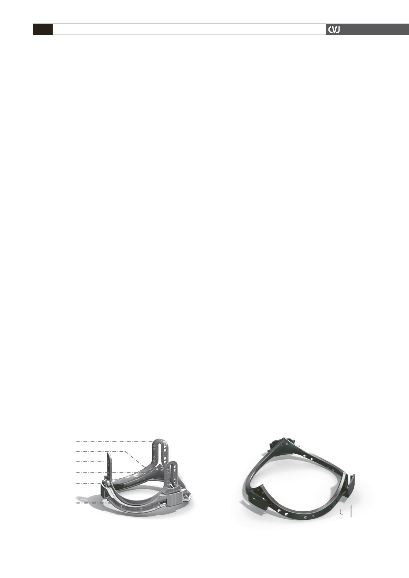
design criteria mentioned. Fig. 1 shows the assembled valve
components without the leaflets, comprising the upper and
lower components of the leaflet-bearing frame, together with
the receptacle, but without the sewing ring in place. Fig. 1 also
shows the continuous gap between the upper and lower frame
components, and the area where the pericardium meets at the
base of the posts in the upper frame. From this base region to
the apex of the post, the pericardium leaflets come into surface
contact with each other and are held in position by a clip that is
located outside the post.
The radial width of the support frame and its receptacle was
kept to a minimum of 2.5 mm along the scallops, and 3.0 mm
at the posts. The valve frame receptacle is intended for supra-
annular insertion. A running 2.0-mm circumferential footprint
of the receptacle will lie outside the confines of the native aortic
valve annulus. The effective orifice of the valve will therefore
be within a 10 to 15% tolerance of the natural orifice of the
native valve. A potential disadvantage is that in some patients,
the openings to the coronary arteries lie just above the frame
annulus, so that the placement of the posts would have to be
rotated and positioned accordingly.
The cross section of the lower frame is hydrodynamically
shaped and flared. The surface that opposes a similar-shaped
surface on the upper frame to form the gap in which the
pericardium is gripped has a width of 1.0 mm and the edges
are rounded to avoid the risk of damaging the pericardium as it
flexes. The complete bottom frame is shown in Fig. 2. The shape
of the lower edge of this component conforms accurately to the
shape of the corresponding surface of the upper edge of the
lower component, allowing a gap between the components that
is inclined at 10 degrees to the horizontal, sloping up toward the
centre of the valve.
The gap between the frames, within which the pericardium
is held, is designed to be on average 300 µm wide (assuming a
pericardium approximately 250 µm thick, with polymer coating
of 25-
µ
m thickness on each side of the gap). The pericardial
thickness may vary between 200 and 300
µ
m, and the thickness
of the polymer coatings will vary depending on the exact nature
of the polymer, its viscosity and drying conditions. Therefore,
a locking mechanism has been designed to allow the upper and
lower components of the frame to be locked with a gap. This
Fig. 1. Image of assembled upper and lower frame and
receptacle.
Post
Scallop
Upper Frame
Lower Frame
Receptacle
Grooved outer
surfaced to
receive sewing
ring
Fig. 2. Image of lower frame.


